

Virtual Local Area Network (VLAN)
In a traditional local network, all switches and all ports are part of the same broadcast domain, so they can communicate with each other. However, there is often a need to divide the network into smaller domains. This may be done to limit network traffic or to improve security.
This can be achieved by using separate cables and switches for each domain, but it is usually more practical to use network switches with VLAN functionality to achieve the same result in a much more flexible way. A VLAN switch can be configured internally so that data is only forwarded between selected groups of ports. From the outside, it will appear as if there are several physically separate switches. This approach is therefore called “port-based”.
IEEE 802.1Q is a standard that describes a more flexible method called “VLAN tagging”. It is based on the switch adding 32-bit information to Ethernet frames to indicate which VLAN group the frame belongs to. This makes it possible to build more advanced VLAN networks where VLANs can be distributed across multiple switches, as VLAN switches exchange traffic via “trunk links”.
All DANBIT switches with VLAN support the IEEE 802.1Q standard, even if it is not mentioned on the product page.
WLAN / WiFi

WLAN (Wireless Local Area Network) refers to a wireless network that works like a wired network, using radio signals instead of cables between participants. See more about building wireless networks on the next page.
By default, a WLAN can be vulnerable and unprotected. To secure a WLAN, it can be protected with a password that is encrypted using a security algorithm (WEP, WPA, or WPA2). It is also possible to hide the name of the wireless network, also called the SSID (Service Set Identifier). This means users must know the name before they can connect.
WLAN is defined by a set of standards called WiFi, based on the IEEE 802.11 standard, which has evolved over time. Common standards include 802.11g (data rates up to 54 MB/s) and 802.11n (up to 150 MB/s). To maintain a stable connection, devices automatically fall back to lower speeds when signal strength is insufficient.
PoE – Power over Ethernet
PoE delivers power to clients via network cables, making separate power supplies unnecessary for devices such as surveillance cameras and serial port servers. PoE equipment is designed to receive supply voltage via network cables. Often, PoE devices can also be powered from an external power supply. Cable length can limit the use of PoE. A newer standard called PoE Plus (IEEE 802.3at) can deliver more power than the current PoE standard (IEEE 802.3af).
General information about midspan and endspan
The PoE standard IEEE 802.3af allows the use of two types of power sourcing equipment: endspan and midspan.
An endspan device (PoE switch) typically supplies power over the data pairs in the network cable (pins 1 and 2, 3 and 6) and is available for 10/100Mbit and 10/100/1000Mbit Ethernet sources. An endspan device combines a midspan injector and a switch. It is installed instead of a standard switch when connected network devices must be powered over the network.
A midspan injector (hub) is installed between a non-PoE switch and the powered device. It is limited to supplying power via the unused pairs (pins 4 and 5, 7 and 8) in a 10/100Mbit network.
General information about VDSL
DSL was the earlier term for Digital Subscriber Loop, which was later renamed Digital Subscriber Line. DSL transmission runs over two copper wires (a standard telephone line). Early DSL could initially transmit 64 kbit/s.
Today, VDSL is used, where “V” stands for “Very high”. The data rate can be up to 25 Mbit/s over short distances on a two-wire connection (approximately 800 m). Over longer distances, the speed drops to 15 Mbit/s at 1.3 km and 5 Mbit/s at 1.9 km, which is the maximum distance. A VDSL connection consists of two units: Master and Slave, which can use up to seven different frequency bands (900 kHz–3.9 MHz, and 4 MHz and 7.9 MHz). The connection uses Quadrature Amplitude Modulation / Discrete Multi Tone, is full duplex with auto-speed, and the next generation is VDSL2 (30 Mbit/s–100 Mbit/s) with a maximum range of 300 meters, using Discrete Multi Tone only.
The units connect to Ethernet and include a built-in splitter, allowing you to connect a PSTN line to the remote unit and a telephone to the local unit. If you only have an older two-wire connection, VDSL is suitable for applications requiring high bandwidth (for example HDTV).
Build your own wireless network
All PCs that need to connect wirelessly to a network must be equipped with a WLAN network card, which can be an internal PCI card, a PCMCIA card, or an external USB device. All types can be used as needed in “Ad hoc mode” or “Infrastructure mode”.
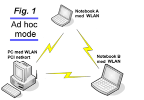
In “Ad hoc mode” (see example in Fig. 1), WLAN/WiFi adapters communicate directly with each other without using a hub, switch, or other equipment, so it is easy to set up. However, all participants must be within range of the others. If two PCs cannot reach each other, other PCs cannot act as “relay stations”.
Wireless range depends heavily on the physical environment. Concrete walls and steel structures can significantly attenuate radio signals. In a typical office building made of lighter materials, using IEEE 802.11g you can typically achieve the maximum transmission speed (54 Mbit) at distances up to 15–20 m. Over greater distances, “auto-fallback” to lower speeds normally occurs (typically 24 Mbps at distances over 30–40 m, and down to 6 Mbps at distances over 80–100 m).
Infrastructure mode
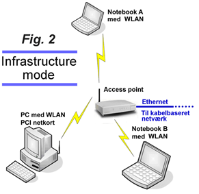
“Ad hoc” networks can work well in private homes and small businesses, but better results are typically achieved with “Infrastructure mode” (see example Fig. 2). Here, participants no longer communicate directly with each other, as traffic always goes through an “access point”. The only requirement is that all participants are within range of an access point. Note that the coverage radius of an access point will typically be twice as large as in “ad hoc mode”, meaning the coverage area is four times larger. By switching to “Infrastructure mode” and using an access point, you get a significant improvement in coverage and stability.
The most important purpose of an access point is to act as the bridge between wireless participants and a wired network. Therefore, an access point is equipped with Ethernet ports that can be connected to a wired network.
Internet connections
In the “Ad hoc” example in Fig. 1, participants can share an internet connection without using a wireless router or access point. If one of the computers in Fig. 1 already has a wired broadband internet connection, it can be shared with the others. In Windows XP this is described as “ICS” (Internet Connection Sharing).
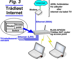
Fig. 3 shows an example of a wireless internet connection using the “Infrastructure” method. A wireless router with an Ethernet port is used for the internet connection, meaning it can be used with a standard ADSL modem with Ethernet output or the type of Ethernet cable modem provided by cable TV internet providers. Both the wireless router and the WLAN/WiFi cards in the wireless participants are used in “Infrastructure mode”.
Mixed wireless and wired network
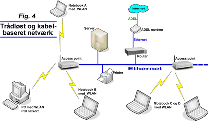
Fig. 4 shows an example of a mix of a wireless and a wired network. It is assumed that both access points and WLAN/WiFi cards are used in “Infrastructure mode”. A traditional wired network is shown, equipped with multiple access points.
Users on the network (both wireless and wired) have access to network resources (servers, printers, internet connection, etc.) in the same way as on a standard network.
General information about WPS
WPS (Wi-Fi Protected Setup) is a wireless networking feature that simplifies connecting to an access point or router with encryption enabled. The connection can be established in several ways.
The two most common are:
- One method uses a PIN code that is printed on the network adapter or provided in accompanying software. This PIN must be entered in the router configuration, after which the connection can be established.
- The other method requires pressing a button on the router and a button on the network adapter (either a physical button or a button in an application) within a short time window, and then the connection is established.
WPS can also improve convenience because the encryption key can be made very complex and does not need to be stored anywhere other than on the router. Many of our network products support WPS.
Note: A security weakness has been found in the WPS protocol. It is therefore recommended to disable this feature if it is not being used. Read more here.
Secure encryption
It is recommended to secure wireless networks with WPA2 (preferably WPA3 where supported) instead of WEP or WPA, as this enables significantly stronger encryption.